|
The fan stacks are used for maximizing the fan efficiency,
for preventing the reverse running of fan, and for minimizing
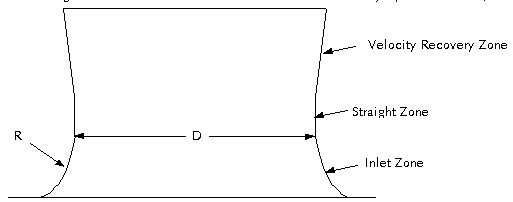
the discharge air recirculation. The fan stack consists
of three major parts as follows;

As the air is induced out
of the plenum chamber beneath the fan, it tends to flow
very predictable streamline into the fan stack. The
inlet section of fan stack must be designed to induce
the air smoothly and to minimize the air turbulence.
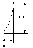
In most cases, R/D = 0.15 or R/D = 0.10 is recommended.
The straight zone of fan
stack is also very important to the fan performance.
The fan blade are deflected downward during the operation
due to the axial load onto the fan blade surface. Therefore,
the movement of fan blade tips must be limited within
the straight zone of fan stack. The minimum height of
straight zone in the fan stack is a summation of the
vertical dimension at the maximum blade pitch angle,
the maximum deflection of fan blades tip, and some extra
allowance.

Once the air properly directed
into the fan stack, the close tip clearance must be
kept. The greater the tip clearance the less efficient
the fan. The space between the fan tip and fan stack
allows the creation of air vortex at the blade tips
which shorten the effective length of the blade, reducing
the fan performance. (A vortex from upper section of
the fan blades back to the low pressure area beneath
the fan allows; this produces a lowered air flow rate
and reduced fan efficiency.)
Close tip clearance minimizes
the magnitude of the disturbances, maximizing the fan
performance. However, the tip clearance must be designed
to accommodate the wind-affected deformation of the
fan stack, thermal expansion of the fan blades, and
the possible build-up of ice inside the fan stack under
the reverse fan operation. Fans are often installed
in cooling tower with the tip clearance of up to 2 inches
because of the manufacturing tolerances inherent in
large fiberglass stack segments.
If the tip clearance is larger
than the below maximum values, a pressure loss due to
the increase of fan stack sectional area will occur.
A rapid decline in the fan efficiency due to the decrease
of total pressure and airflow will be resulted in and
the brake horsepower under this situation will be slightly
decreased.
| Fan
Diameter |
Minimum |
Maximum |
| up
to 9 feet |
1/4" |
1/2" |
| 10
- 14 feet |
3/8" |
3/4" |
| 16
- 20 feet |
1/2" |
1" |
| 22
- 30 feet |
3/4" |
1-1/4" |
The power consumption is
generally decreased as much as the tip clearance is
increased, since the volumetric air flow rate is significantly
decreased. The efficiency at the larger tip clearance
is decreased. The efficiency of fan at the larger tip
clearance is decreased, because the input power is not
reduced as much as the airflow is decreased.
At a slightly tapered exit
cone the velocity pressure compared to the plane of
fan is significantly reduced. The recovery of velocity
pressure is converted into static regain which lowers
the total pressure requirements of the fan.
A poorly designed and fabricated
fan stack is a potential cause of poor air distribution,
low fan stack efficiency, and significant vibration
of fan stack due to the resonant frequency of fan. For
high efficient fan stack design, the normal height of
total fan stack is ranged in the 0.6 to 1.0 to the fan
diameter. The taller height of fan stack than 1 x fan
diameter does not useful for the velocity recovery and
only makes the problems like the heavy fan deck load
and higher wind load. The short height of fan stack
is making a problem of the reverse running of fan due
to the external wind under the situation of the fan
is off.
| 
|
If
the power is applied to the motor under the fan
is reversibly running, all the mechanical equipment
as well as fan, gear reducer, and coupling shaft
shall be broken.
So, the height of fan
stack must be taller than the fan diameter by
at least0.6 times and sometimes the back stop
device, which protects the reverse running of
fan, shall be installed to the motor or gear reducer. |
Example 7-1.
Estimate the height of inlet, straight, and velocity
recovery zones of fan stack for the 28 feet of fan in
the diameter and 10 feet of fan stack in the height.
(Solution)
1) Fan Inlet Zone
| |
Let's
use the R/D = 0.15.

|
Inlet
Zone Height
= 0.15 x Fan Dia.
= 0.15 x 28 feet
= 0.15 x 28 x 12
= 50.4 inch
This inlet shape was
proven to be the ideal inlet shape, because the
air flows along the wall with a uniform velocity
and to the fan with the slightest possible turbulence. |
2) Straight Zone
- Vertical Dimension of
Blade Tip @ Max. Pitch Angle: 5.73 inch
- Maximum Deflection of
Blade Tip: 14 inch
- Extra Dimension from the
trailing edge of blade: 6 inch
- Then, the height of straight
zone is 25.73 inch (= 5.73 + 13 + 6)
3) Velocity Recovery Zone
| Velocity
Recovery Zone Height = Total Fan Stack Height
- Fan Inlet Zone Height - Straight Zone Height
=10 x 12 - 50.4 - 25.73 =43.87 inch |
Example 7-2.
Calculate the velocity recovery at the above given design
conditions.
(Solution)
There is no regulation in estimating the velocity recovery
at the fan stack, which is generally accepted by every
one, and the designers have to decide it with the experience.
For the angle of taper, 7 degree is most efficient through
the a lot of tests. The following formulas could be
used for estimating the velocity recovery.
1) Formulated by Hudson Products
Corp.
| Basically,
Hudson's velocity recovery formula is based on
the 7 degree of taper angle and 70% of fan stack
efficiency.
Velocity Recovery =
70% of Fan Stack Efficiency x (Velocity Pressure
@Fan - Velocity Pressure @Top of Fan Stack) |
2) Formulated by MRL Corp.
| The
degree of taper at the venturi zone is same as
Hudson, but the fan stack efficiency is differently
obtained as 0.8 - 0.2 x (Venturi Height / Fan
Diameter)
Velocity Recovery = 0.8 - 0.2 x (Venturi Height
/ Fan Diameter)
x (Velocity Pressure @Fan - Velocity Pressure
@Top of Fan Stack) |
In order to obtain a velocity
pressure at the top of fan stack for a given fan stack,
the area at the top of fan stack must be calculated
first as follows;
Diameter of Fan Stack Top
= Fan Diameter + 2 x Tan 7o x Venturi Height
Area of Fan Stack Top = 0.7854 x (Diameter of Fan Stack
Top2 - Air Seal Disk2)
= 0.7854 x [28 + 2 x Tan 7o x 43.87 / 12)2
- (88 / 12)2] = 613.6 ft2
Air Velocity @Fan Stack Top
= Air Volume @ Fan / Area of Fan Stack Top = 1019716.289
/ 613.6 = 1,661.86 ft/min
Velocity Pressure @Fan Stack
Top = (Air Velocity @ Fan Stack Top / 4008.7)2
x (Air Density / 0.075) = (1661.86 / 4008.7)2
x (0.0696 / 0.0750) = 0.1594 inch Aq.
Let's fan stack efficiency
using the formula of MRL Corp.
Fan Stack Efficiency = [0.8
- 0.2 x (Venturi Height / Fan Diameter)] x 100(%) =
{0.8 - 0.2 x [(43.87 / 12) / 28]} x 100 = 77.4%
Velocity Pressure @ Fan =
(Air Velocity @Fan / 4008.7)2 x (Air Density
@Fan / 0.075) = (1778.0 / 4008.7)2 x (0.0696
/ 0.0750) = 0.1825 inch Aq.
Velocity Recovery = Fan Stack
Efficiency x (Velocity Pressure @Fan - Velocity Pressure
@Fan Stack Top) = 0.774 x (0.1825 - 0.1594) = 0.0178
inch Aq.
(Note: The reason why the
area of air seal disk must be subtracted from the above
equation in calculating the area of fan stack top is
because the air streamline does not exist above the
air seal disk.)

|