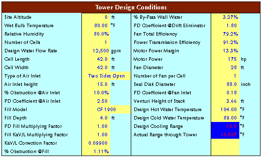
The following steps are being practically applied to design
the cooling tower and the current computer thermal programs
are based on this concept.
Example 13-1.
Determine the cold water temperature for the following
conditions.
First Step: Find a
dry bulb temperature at the tower inlet.


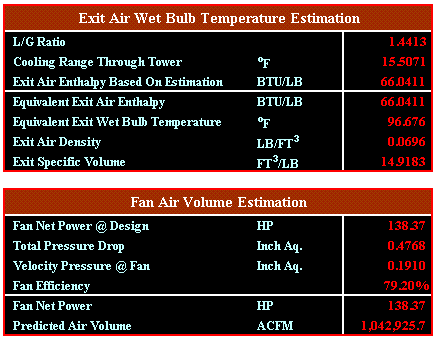
Second Step: Find
an exit air temperature and air volume of fan. The net
fan power is determined from the relation of Motor HP
x (1 - Motor Margin) x Power Transmission Efficiency.
It is to iterate the calculation until the net fan power
obtained from this equals to the fan bhp which is formulated
with (ACFM x Total Pressure) / (6356 x Fan Efficiency).
Two variables in the fan bhp equation are unknown, but
can be computed from below relationships.
The main idea is to iterate
the calculation until the net fan power equals to the
calculated fan bhp varying the air volume, static pressure
and tower exit temperature at the fan.
The air mass flow rate through
the tower is always constant because the air mass is
being considered as dry gas. Then, the air mass flow
rate and L/G Ratio can be obtained as below:
Air Mass Flow Rate = Air
Volume @ Fan / Specific Volume @ Fan
The L/G Ratio =Water Flow
Rate in gpm through Tower x (500/60) / (Air Volume @
Fan / Specific Volume @ Fan)
Water flow rate in gpm through
tower in this formula is a net water flow rate considering
the % by-pass wall water. That is, Design Water Flow
Rate x (1 - % By-Pass Water ).
In order to obtain the specific
volume the tower exit temperature should be computed
first. The exit temperature requires L/G ratio as the
exit air enthalpy (ha2 = ha1 +
L/G x Range) is a summation of tower inlet air enthalpy
and L/G x cooling range. L/G ratio can be given or calculated
if the tower dimensions are given and the value of fill
characteristic is known.
The air volume at each location
of cooling tower is obtained from the relationship of
Air Mass Flow Rate x Specific at each location, and
then the air velocity at each location is calculated
by dividing the air volume by the net area at each location.
The total static pressure is a summation of pressure
drops obtained from each location.

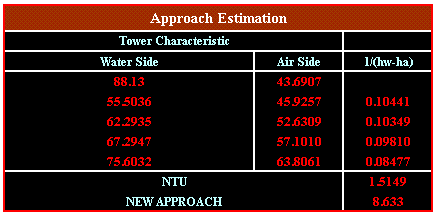
Third Step: Calculate
the tower characteristic in accordance with above results.
To calculate this the performance data of fill manufacturer
is required.
Fourth Step: Determine NTU(=KaV/L)
satisfying the value of tower characteristic by the
method of iteration with changing the approach.

Download
the example file, Version ID-THERMAL/TOWER (idthermal.zip)
This file covers the example no. 13-4, too.
Therefore, Actual Cold Water
Temperature = Wet Bulb Temperature + Approach = 80.00
+ 8.633 = 88.63oF
Above the enthalpies for
water side were computed at the below temperatures.
- Water Temperature @ 0.1
x Range = Wet Bulb Temperature + Approach + Range
- New Range + 0.1 x New Range
- Water Temperature @ 0.4
x Range = Wet Bulb Temperature + Approach + Range
- New Range + 0.4 x New Range
- Water Temperature @ 0.6
x Range = Wet Bulb Temperature + Approach + Range
- New Range + 0.6 x New Range
- Water Temperature @ 0.9
x Range = Wet Bulb Temperature + Approach + Range
- New Range + 0.9 x New Range
Also, the enthalpies for
air side were based on the followings.
- Enthalpy @ 0.1 x Range
= Inlet Air Enthalpy + L/G x 0.1 x New Range
- Enthalpy @ 0.4 x Range
= Inlet Air Enthalpy + L/G x 0.4 x New Range
- Enthalpy @ 0.6 x Range
= Inlet Air Enthalpy + L/G x 0.6 x New Range
- Enthalpy @ 0.9 x Range
= Inlet Air Enthalpy + L/G x 0.9 x New Range
To be continued. Please press the next button....
|