|
The characteristic curve serves as a measure of the
capability of the cooling tower to which it applies.
It relates the familiar design term of KaV/L and L/G,
and is of the form;
KaV/L = C L/G-m
C and m are constant for
a given cooling tower and are determined by the characteristics
of the fill, while m is determined by end effects. The
characteristic curve is used in conjunction with a KaV/L
vs L/G relationship to determine performance. This curve
may be termed "Design requirement" curve,
since it is a measure of the degree of difficult of
the design requirements, and has nothing to to with
the physical characteristics of the tower. It is constructed
by assuming values of L/G and computing the corresponding
values of KaV/L using the following equations.
 ----------------
Eq. 21.1 ----------------
Eq. 21.1
where, hw is the enthalpy
of air-water vapor mixture at the bulk water temperature
and ha is the enthalpy of air-water vapor mixture at
the equilibrium wet bulb temperature.
The intersection of the characteristic
and design requirements curves locates the design point.
The manufacturer predicts that, when operating at the
L/G value so located and at design water circulation
rate, inlet water temperature, and wet bulb temperature,
design outlet water temperature will be attained.
The test value of L/G is
determined from Eq. 22-1, 22-10 & 22-12 which were
derived in the chapter 22. From these equations, L/G
dsn is the L/G value at the intersection of the characteristic
and design requirement curves. The corresponding value
of KaV/L is computed from above Eq. 63-1 using the test
wet bulb and water temperatures. This point is then
plotted, and a line a parallel to the characteristic
curve is drawn through it. The intersection of this
line and design requirements curve locates the L/G capability
at the design conditions.
Example 21-1:
Determine the tower capability using the characteristic
curve for the initial design conditions and below test
records.

(Solution)
First, let's compute the dry bulb temperature
for the design and wet bulb temperature for the test
conditions.
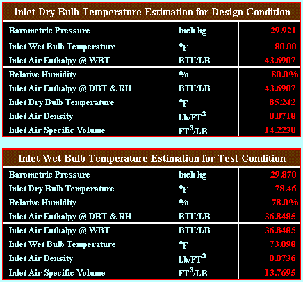
Exit Enthalpy @ Design =
Inlet Enthalpy @ Design + L/G design x Range @ Design
= 43.6907 + 0.8600 x (115 - 85) = 67.4907 BTU/LB

Exit Enthalpy @ Test = Inlet
Enthalpy @ Test + L/G test x Range @ Test
The L/G test is calculated
from the below formula.
L/G test = L/G design x (Water
Flow test / Water Flow design) x (Fan BHP design / Fan
BHP test)1/3 x (Exit Air Density test / Exit
Air Density design)1/3 x (Exit Air Specific
Volume test / Exit Air Specific Volume design)
Derivation details of L/G
Test are as below:
| Fan
BHP |
=
VOL x TP / (6356 x Fan Effi.)
= VOL x (VP + SP) / (6356 x Fan Effi.)
= VOL x (1/2g x Density x Vel2 + K
x 1/2g x Density x Vel2) / (6356 x
Fan Effi.)
= VOL x Density x Vel2 x (1 + K) /
1/2g / (6356 x Fan Effi.)
= VOL x Density x Vel2 x (Area2
/ Area2) x (1 + K) /1/2g / (6356 x
Fan Effi.)
= VOL x Density x VOL2 x 1 / Area2
x (1 + K) /1/2g / (6356 x Fan Effi.)
(The term of 1 / Area2 x (1 + K) /
1/2g / (6357 x Fan Effi.) could be considered
as a constant under the assumption that the fan
efficiency at the design conditions is equal to
the fan efficiency at the test conditions.) |
Then, above equation could
be expressed to Constant = Fan BHP / (VOL3
x Density). Therefore, the following relationship is
established.
Constant = BHP dsn / (VOL
dsn3 x Density dsn) = BHP test / (VOL test3
x Density test)
Let's rewrite this relationship for the term of Vol
test.
VOL test3 = (BHP test / BHP dsn) x (Density
dsn / Density test) x VOL dsn3
| VOL
test |
= (BHP
test / BHP dsn)1/3 x (Density dsn /
Density test)1/3 x VOL dsn
= (BHP test / BHP dsn)1/3 x (Density
dsn / Density test)1/3 x L dsn / (L/G
dsn) x SV dsn (VOL dsn = L dsn / (L/G dsn) x SV
dsn) |
| L/G
test |
=
L test / G test
= L test / (VOL test x SV test)
= L test x SV test / VOL test
= L test x SV test / ( (BHP test / BHP dsn)1/3
x (Density dsn / Density test)1/3 x
L dsn / (L/G dsn) x SV dsn)
= L/G dsn x (L test / L dsn) x (BHP dsn / BHP
test)1/3 x (Density test / Density
dsn)1/3 x (SV test /SV dsn) |
Then,
| L/G
test |
=
0.860 x (9,150 / 10,000) x (240.0 / 216.0)1/3
x (Exit Air Density test / 0.0693)1/3
x (Exit Air Specific Volume test / 15.0327) |
To be continued. Please press the next button.... |


