|
Nozzles of above type can improve the thermal performance
of a film fill pack by at least 10% when compared to
other typical industrial nozzle systems. This performance
improvement is developed by the fact that state of the
art counter flow nozzles assure more complete utilization
of the high performance fill.
The nozzle arrangement, and
the design of the tower structure in the spray chamber,
are critical to provide uniform distribution to the
top of the fill. The placement of the nozzles must accommodate
the tower geometry and still provide even coverage for
all parts of the plan area. In general, a criterion
such as 90% of the plan area within 5% of the average
gpm/square foot, and no areas varying more than 10%
from the average will still require several percent
conservatism in the thermal performance.
Structure in the spray chamber
should be avoided, to prevent spray pattern interference
and because any water hitting it tends to fall in concentrated
zones on the fill. The impact depends entirely on the
extent of structural blockage but can be very substantial
for large elements like distribution pipes places within
the spray zone in case of up-spray.
Spray water which hits walls
or partitions may bypass the fill altogether, with direct
impact on performance. Some hollow cone nozzle designs
are more prone to structure and wall interference due
to the requirement for large overlapping spray patterns.
Providing uniform coverage to the edges of the fill
requires nozzle placement near the walls to maintain
the overlap pattern. As a result, a significant part
of the water from the edge nozzles becomes wall water.
Of importance also, is the difficulty in producing in
test cells the overlap pattern which will occur in full
scale. As a result, overlapping pattern nozzle designs
exhibit poor correlation in scale up from test cell
to full scale.
The influence of the spray
system design on performance is dramatic. Even small
changes in the layout of a good spray system, or variations
on a nozzle design can have an effect on tower performance
of 10% or more. For this reason, it is absolutely imperative
that the performance of the fill and spray system be
tested as they will be installed. Fill performance data
in only valid with the exact spray system configuration
used in the test.
(4) Air Distribution: Three
variables control the distribution of air to the fill
in a counter flow configuration. The first is the air
inlet geometry. The second is called the pressure ratio.
The third is the fan coverage over the eliminators.
Extensive aerodynamic modeling
studies have been conducted to evaluate the impact of
the air inlet design on air distribution, and therefore
on performance. It is especially important with film
fill that air flow reach the entire plan area, including
the region adjacent to the air entrance. Any region
having significantly reduced air flow will effectively
allow a bypass of hot water to the cold water basin.
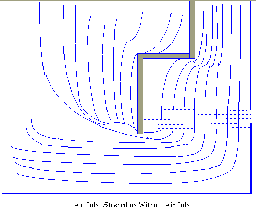
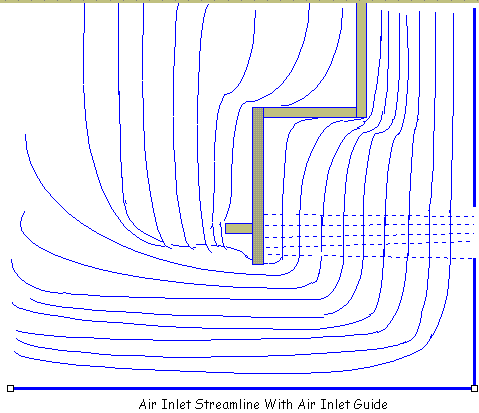
Studies showed that the portion
of fill plan area adjacent to the air inlet plane is
substantially starved from air flow. Since the air approaching
the tower is coming from above the air inlet as well
as horizontally, the air has a large downward component
adjacent to the tower casing. When this air stream passes
the air inlet plane, it is still moving downwards, and
does not turn into the fill nearest the inlet. In round
tower, this can become a very significant percentage
of the total area. In a rectangular tower the effect
is still significant, but less.
To circumvent the loss of
effectiveness of fill near the air inlet, studies have
been conducted of designs which change the point at
which the air entering the tower begins to turn toward
the fill. Both physical and mathematical modeling have
been used for this purpose. For the mathematical simulation
of the flow patterns, a model called FLUENT by Creare
R&D, Inc. has been utilized. The below figures show
flow streamlines generated by using FLUENT to simulate
the work done in previous physical models of mechanical
draft with and without air inlet guides.
Critical to the effectiveness
of any design, even with an inlet air guide, is that
structural interference near the fill and air inlet
be minimized. Since inlet velocity is highest in this
zone, the wakes behind structural elements can shadow
significant areas of fill. Structural interference in
this area is meticulously avoided to maximize the effectiveness
of a design. The wakes around structural elements at
the air entrance also lead to growth of ice in freezing
conditions, so avoidance of structure in the air entrance
reduces tendencies for icing problems as well.
Baffles used for the purpose
of changing the direction of air flow in a uniform parallel
manner, also utilized to prevent water droplets from
splashing out of the tower on their descent through
the structure.


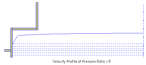
The second variable, the
pressure ratio, is the ratio of system pressure drop
(from the air inlet to the eliminator exit plane) to
velocity pressure at the average entrance velocity (=
air inlet velocity). The pressure ratio reflects the
ratio of resistance to available entering air energy.
The higher the ratio, the better entering air will be
spread out before entering the fill. The lower the pressure
ratio, the less uniform, and less stable the distribution
of air flow becomes. The below figures show the velocity
profile at the top fill. The degradation of air flow
uniformity is readily apparent, particularly at the
inlet. ( Pressure Ratio = Static Pressure / Velocity
Pressure at Air Inlet)

It should be noted that ambient
winds can decrease the effective pressure ratio in relation
to the square of wind speed. Added entering air velocity
due to winds increases the velocity pressure as the
square of velocity. A safety margin is necessary to
prevent moderate (10 mph = 4.47 m/s) winds from degrading
air distribution. The chosen practice is not to apply
towers below a pressure ratio of 5, which is of importance
particularly for highly evaluated cases.
The tendency for optimized
selections is toward selections with low pressure drop
(low fan power, or draft requirement) and high entrance
velocity (low pump head). The pressure ratio limitation
is a frequent limiting factor in optimization, so that
a manufacturer who is unaware of the limitation could
have a better evaluated bid - which is not likely to
perform as the manufacturer might expect. A manufacturer
who recognizes the limitation may be unable to respond
in this case, while an unaware manufacturer and the
user may discover a serious performance problem after
the tower is in service.
Modeling and full scale tower
studies have shown that fan plenum pressure drop is
related to fan coverage, the third variable. Inadequate
fan coverage has been shown to lead also to poor air
flow distribution over the fill plan area. Fan coverage
is a function of the size of the fan deck opening, the
cell size, and the plenum height.
The relationships involved
are complex and represented in practice by an empirical
computer model, but an approximate rule of thumb which
has been shown to provide good air distribution and
a low plenum pressure drop is as follows; If a circle
is projected on the eliminator plan area at a 45 degree
angle from the fan cylinder opening, the percentage
of the eliminator are covered by the projected circle
is the percent fan coverage. A fan coverage percentage
of 80% or greater generally limits the plenum pressure
drop to about 10% of the total system pressure drop,
and provides good air distribution.
Ignoring this sort of guideline
will allow a shorter plenum height, and lower cost tower,
but higher plenum pressure drops and uncertain air distribution
lead to lower and less predictable performance.
(5) Exit Air Velocity: Low
fan exit velocity have a two-fold effect on susceptibility
to influence by ambient winds. First, at low exit velocity
relative to ambient wind speed, the effect of wind is
greatest on the velocity profile leaving the fan stack.
With tall velocity recovery stacks, the effect is limited
primarily to a reduction of the velocity recovery stack.
Depending on the magnitude of recovery expected in relation
to the total system head, this can be a significant
loss. The shorter the recovery stack, or the closer
ambient wind can penetrate the cylinder toward the fan
itself, the greater will be the direct influence on
the fan efficiency. For fans and recovery stacks as
commonly applied in industrial applications, a minimum
stack exit velocity is approximately 1.4 times the maximum
wind speed for guaranteed tower performance (10 mph
= 880 fpm). Use of nay lower exit velocity requires
substantial performance conservatism to compensate for
wind effects.
It should be noted also,
that tower performance capacity at lower exit velocities
relative to the ambient wind speed becomes increasingly
sensitive to the wind and inherently as unsteady as
the wind speed is variable. It is entirely in the tower
owner's best interest to avoid a tower configuration
which will have highly variable performance in winds
from this effect alone.
The second consequence of
excessively low stack exit velocity is the tendency
for effluent air to be caught in the ambient wind stream
and entrained in the aerodynamic wake downstream of
the tower. Since the tower generally has an air entrance
face on the downstream side, a portion of the effluent
air is "recirculated" back through the tower.
The effluent air is, of course, at a higher wet bulb
temperature, so the tower is effected as if subject
to hotter ambient temperature.
A considerable research program
has been conducted over the course of many years to
model recirculation, and substantiate the results with
field testing. Much of the work has been done in cooperation
with the Iowa Institute of Hydraulic Research, University
of Iowa City, Iowa. More recent work has been done in
a proprietary Low Speed Wind Tunnel. This modeling has
extended to the most current counter flow mechanical
draft configurations, and is confirmed by field testing.
It is clear that a significant
penalty should be included in terms of increasing the
entering wet bulb temperature at design ambient wet
bulb temperature of rectangular towers if a low ratio
of fan stack exit air velocity to the ambient wind speed
is to be used, particularly below a ratio of 1.4 (1,200
fpm exit/880 fpm guarantee wind speed). Round towers
require a much smaller, but still meaningful recirculation
allowance for entering wet bulb temperature above ambient.
The entering wet bulb specified should be linked to
the minimum exit velocity specified and the expected
wind speed, with the assistance of cooling tower manufacturer.
|