| Over
the past three decades, mechanically drafted cooling
towers increased in cell size due to economies
of scale. The size of induced draft fans used
on such towers trended from around 14 feet in
diameter to diameters in the 30-to 40- foot range.
Traditionally, these fans were mounted in right
angle, speed reducing gear boxes which were driven
via solid or small diameter tubular drive or coupling
shafts by horizontal motors mounted outside the
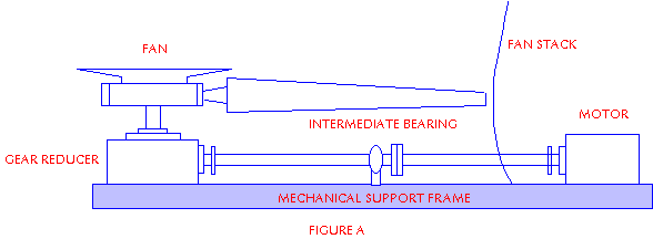
fan stacks. Larger fans required longer shafts
which led to the use of intermediate drive shaft
support bearings, and frequently, intermediate
flexible couplings (see below figure A).

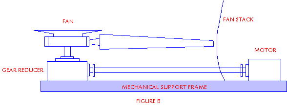
Several cooling tower
designers selected long, single-piece, hollow,
large diameter flexible coupling drive shafts
see below figure B) as a more reliable alternative
to this evolution of the more traditional slender
shafts.


Early installation
with large fans utilized drive shaft systems similar
to that depicted in figure A. These installations
were plagued with intermediate support bearing
failures along with occasional shaft or intermediate
coupling failures and associated fan damage. Fan
damage caused by flying sections of shafting was
reduced by the addition of shaft guards. Refinements
in intermediate bearing lubrication systems reduced
but did not eliminate bearing failures. In short,
the maintenance headaches associated with these
installations were causing unnecessary cell down
time.
With respect to cooling
towers that rely on mechanical draft cooling towers,
reductions in tower capability at the peak ambient
temperature time translated directly into costly
curtailment of plant operation. This was and is
particularly a problem in some cooling towers
where many of cooling tower with summer peak loads.
The use of larger
diameter single-piece drive shafts circumvented
the above problems by deriving their support only
from the motor and the gear box without requiring
additional bearings. The Design and Application
section below elaborates on these and other advantages.
However, single-piece drive shafts are not without
their own idiosyncrasies. The problem is dependent
on tower type (cross flow or counter flow), and
types of fill used, and the height of the tower.
All are related to the thermal expansion.
|