|
1) Reaction Chemistry
A chlorine leak in the room
housing the chlorine cylinders / containers / tanks
or in the chlorinator room should be neutralized by
means of neutralizing solution (Soda, Sodium Hyposulphite).
Mainly caustic soda solution (NaOH) is used for neutralization
of chlorinated air.
The chemical reaction of
chlorinated air and caustic soda (Sodium Hydroxide)
is:
Cl2 + 2NaOH
+ H2O = NaCl + NaOCl + 2H2O +
44,600 Btu/mole Cl2
Through the contact of chlorinated
air and neutralization solution, the concentration of
exhausted air could be reduced to 1ppm. Two moles of
sodium hydroxide (80 pounds) is required to neutralize
each mole of chlorine (70.9 pounds). The amount required
to neutralize the 1 pound of leaked Cl2 is
obtained by the below formula;
NaOH = 80.0 / 70.9 = 1.13
times to Cl2
The 20% by weight of sodium
hydroxide is usually used to neutralize the chlorine
gas considering the freezing point in the winter. Fig.
9-1 is showing the relationship between the temperature
and percent of NaOH. Each gallon of 20% solution contains
2.04 lbs of NaOH.
2) Maximum Room Initial Concentration
This is obtained from
Maximum Room Initial Concentration
= (Rate of Gas Vaporization / Rate of Ventilation of
Blower) x 106 (ppm).
3) Chlorine Concentration
vs. time
By performing a material
balance, the following differential equation is obtained
for the decrease of chlorine vapor in the room as a
function of time.

Where,
V = room volume
c = Cl2 vapor concentration in room, ppm
QG = room ventilation rate, ft /min
t = time, min
Upon integrating, the following
equation is obtained:
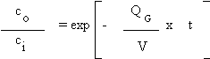
Where:
Ci = initial chlorine vapor concentration,
ppm
Co = chlorine vapor concentration at any
instant, ppm
4) Sump Temperature Rise
Neutralization of chlorine
with sodium hydroxide is an exothermic reaction. The
heat of reaction is 44,600 Btu/mole of chlorine. Reaction
is in liquid phase. If there is no heat loss to the
air and other components of neutralization system, the
temperature rise of sodium hydroxide solution can be
calculated from the following equation:
H = mCpDT
Where,
H = total heat released by reaction, BTU
m = total weight of caustic solution, lb
Cp =heat capacity of causitic solution, BTU/lb
DT = temperature rise, oF
Heat capacity for 20% by
weight caustic solution is 0.9 Btu/lb. One (1) gallon
of 20% NaOH is equal to 10.21 lbs.
5) Chemical Utilization during
Periodic Equipment Checkouts
The neutralization system
is a safety device to be run when the chlorine gas is
leaked. Since this system is not continuously being
operated, it is essential to operate the system periodically
for preventing a possible malfunction of rotating parts.
In general, it is highly recommended to checkout the
system weekly.
Carbon dioxide (CO2)
will be absorbed by the caustic solution during bi-weekly
testing of the system. The reaction between sodium hydroxide
and carbon dioxide is:
CO2 + 2NaOH =
NaCO3 + H2O
Two (2) moles of sodium hydroxide
(80 pounds) is required to react with each mole of carbon
dioxide (44 pounds). Ambient air contains 0.033% by
volume (or mole) of carbon dioxide. Each mole of air
at ambient conditions occupies a volume of 386 cubic
feet. Therefore, 3,000 cfm of air blower is equal to
7.77 moles/min. The carbon dioxide flow rate will be
0.11 lbs/min. Caustic consumption for each minute of
neutralization system testing is 0.21 pounds/min. If
the system testing lasts 15 minutes, then the weekly
caustic consumption is 3.0 pounds. After one (1) year
of regular weekly check-out, the total caustic used
is: 3.0 x 52 = 156 lbs/year. About 30 gal. of 50% of
caustic solution has to be added into the NaOH solution
tank every year. (50% caustic =6.643 lbs/gal of NaOH)
6) RJ Scrubber System
This scrubber system was
designed to meet the Uniform Fire Code (revised 1990),
Section 80.303 of Article 80 as it pertains to indoor
storage of compressed gases. It was specially designed
to meet the UFC maximum allowable discharge concentration
of the Cl2 vapor, to one-half of IDLH (Immediate Danger
to Life and Health) at the point of discharge to the
outside atmosphere. For chlorine, the IDLH is 30 ppm.
Therefore the maximum allowable discharge concentration
in the scrubber vent stack is 15 ppm as stated in the
UFC. The RJ scrubber, though, is designed to treat a
release rate much higher than the UFC requirement. A
full scale test with a chlorine rate at about 100 lb/min.
resulted in vent stack chlorine concentrations of less
than 4 ppm. The entire unit is a skid-mounted package
measuring 16 feet long 8 feet wide and 8 feet high.
(1) Scrubber
This is a single-pass three
stage absorption system that operates entirely under
a vacuum (negative pressure), including all the ducting.
This eliminates the possibility of any release of chlorine
contaminated air. This system is shown in Fig. 9-2.
The three stages of absorption consists of one horizontal
spray scrubbing stage, followed by two horizontal cross-flow
packed bed sections. The design of each stage provides
an overall performance of 99.998% removal of the chlorine
vapor in the vent discharge. This automatically guarantees
that the removal efficiency on a once through basis
will easily neutralize the worst-case chlorine leak
occurrence. The movement of air through the scrubber
is provided by a 5 HP 3000 cfm exhaust fan.
(2) Caustic Storage
This amounts to about 2400
gallons of 20 percent NaOH solution which is about 85
percent excess caustic over the theoretical requirement.
This means that the maximum possible concentration of
hypochlorite after the neutralization of a capacity
leak would be less than 12.5 percent.
(3) Activation System
A chlorine leak detector
activates the scrubber system in two steps:
- The caustic recirculating
pump is started to provide proper atomization for
the first stage plus the proper wetting of the packing
material in the other two stages before the exhaust
fan is activated.
- After a 5 seconds interval
of step one, the 3000 cfm exhaust fan is then automatically
started and this begins the scrubbing of the contaminated
air. This interval before the fan is actuated is not
nearly long enough to change the air pressure in the
room. This automatic sequence during the initial start-up
prevents the discharge of any partially treated contaminated
air before the scrubber is operating at design conditions.
(4) Absorption Details
The absorber is located on
top of caustic tank which is an integral part of the
system. The caustic solution is recirculated continuously
through the scrubber at the rate of 550 gpm at 25 psi
which means that this is classified as a "low pressure
system". The recirculating pump is 20 HP. The scrubbed
air passes through a mist eliminator before it is discharged
to the outside atmosphere. The discharge is monitored
by an EIT series 4000, vent stack monitor. The scrubber
provides a vapor residence time of 5 seconds which is
much longer than in a venturi scrubber.
(5) Major System Features/Advantages
J has conducted full scale
tests of two RJE Vapor Scrubbing Systems during April
1992 at a nationally recognized testing laboratory accredited
by the International Conference of Building Officials
(ICBO).
Testing was performed under
rigidly controlled procedures with continuous on-line
data recording and video taping of each of the tests.
Liquid chlorine was released directly from the cylinders
in a specially designed flash room (13' x 12' x 12').
The systems were evaluated with chlorine release rates
from 30 lb/minute to 100 lb/minute.
The Uniform Fire Code requires
a maximum concentration of chlorine in the scrubber
exhaust of 15 ppm. The chlorine concentration in the
RJE scrubber exhausts were 2 ppm or less during all
tests.
In addition to proven system
designs, RJE scrubber system offers many advantages
that are not available with conventional systems.
- Conservative Design:
Although design requirements are based on the UFC
release rate of 78 lb/min, the scrubber system designed
for 3,000 cfm is capable of neutralizing completely
more than 500 lb/min of chlorine vapor per minute
on a once through basis. This could be equivalent
to a complete cylinder failure with an average 20%
flash-off rate.
- Low Profile: With a special
design concept, our system provides the highest scrubber
performance (three stages) with very low profile.
The overall system size is about 15' L x 8' W x 9'
H.
- Low Horsepower: RJE full
scale system only requires about 1/2 to 2/3rd the
horsepower, because of low pressure recirculation
of chemicals. The table below shows the horsepower
required for RJE system compared to an eductor type
system.
|
Air Flow Rate,
cfm |
RJE Type |
Eductor Type |
|
3000 |
25 |
40 |
|
4000 |
27.5 |
60 |
|
5000 |
27.5 |
60 + |
- Induced Draft Fan: This
fan provides "negative pressure" throughout
the system, including the room, ducting, and scrubber.
- Low Pressure Recirculation:
30 psig (vs. 70 psig) further enhances the safety
of the system.
- Economics: Because of
the low profile and special design, this system is
delivered as a completely skid mounted, piped, wired,
and factory tested unit, thus reducing installation
costs tremendously.
References
1. Chlorine Scrubbing System, Chlorine Institute, Inc.
2. Chlorine Handbook, George White
3. RJ Technical Manual
|


