| All
coupling types and designs are subjected
to common design criteria.
(1) Transmit Torque: Torque is transmitted
from the shaft to the hub via key and keyway.
The following specifications should be included:
* AGMA Class I Clearance fit
bores (reference AGMA 9002-A86)
* Standard width and depth
keyways (commercial fit key - reference
AGMA 9002-A86)
* One self-locking set screw
over the key. A second set screw at 90*
can be provided for more
positive
retention.
* Minimum let length should
fill the entire hub keyway.
* A 2.0 minimum service factor
based on motor nameplate horsepower. Coupling
must be rated
for peak
torque produced by motor.
(2) Misalignment: The ability to accept
misalignment is another prime function of
couplings. Shafts become misaligned as a
result of many natural and unavoidable causes.
Heat, vibration, bearing wear, the setting
of foundations, etc. all tend to alter initial
alignment. In general, coupling life is
increased when shafts are initially aligned
very carefully.
* Aligned shafts. When two
shafts are coaxial.
* Parallel offset misalignment.
When two shafts are not coaxial but their
axes are not parallel.
* Angular misalignment. When
two shafts are not coaxial but their axes
are not parallel.
| a.
symmetrical angular misalignment.
When the axes of the two shafts intersect
midway between the shaft ends.
b. Non symmetrical angular misalignment.
When the axes of two shafts intersect,
other than midway between the shaft
ends. |
* Axial misalignment. Where
the shafts are parallel but move in and
out relative to each other.
(3) Corrosion Resistant: Corrosion resistance
is a criterion which must consider the specific
cooling tower conditions encountered. The
life of a coupling will be affected by a
corrosive chemical attack of its components.
Many forms of corrosion exist, and any one
of them can be detrimental to the life of
a coupling or other components.
(4) Resonant Frequency: The first lateral
critical speed of a cooling tower coupling
and drive shaft assembly should b greater
than 1.3 times the maximum operating speed.
Higher safety factors may be applied to
longer shafts. Addax is using two safety
factors for (1.35 or 1.40) Composite Coupling
Shafts and you can choose one of them. The
past experience with Addax Composite Shafts
is that the 1.4 safety margin is conservative
and there is no problem with using 1.35
safety margin. The first critical RPM of
a simply supported coupling and drive shaft
assembly is approximately obtained from:
Critical Speed = (K/L2) x (OD2
+ ID2)0.5
Where, K = 3.0 x 10⁶ to 10.0
x 106 depending on coupling flexibility
L=
DBSE OD & ID = outside & inside
diameter shaft spacer tube
(5) Forcing Frequency: The term of "Forcing
Frequency" is used to describe a vibration
pulse that may be excited a response from
an element of another system during operation.
Forcing frequencies are; blade pass frequency,
acceleration/ deceleration pulses from couplings,
impulses from reciprocating engines or motors
and gear mesh frequencies. These are all
examples of the generic term of "forcing
frequency". Forcing frequencies of
concern in cooling towers are blade pass
and gear mesh frequencies.
There are three
natural critical frequencies of concern,
a. Axial Natural Frequency (ANF) relates
to the axial stiffness of composite tube
and spring rate of flexible element;
b. Torsional Natural Frequency (TNF) relates
to the torsional stiffness of the composite
tube, the spring rate of the connected shafts
of motor & gear reducer, and the rotational
inertia of the motor and gear reducer and
drive shaft;
c. Lateral Natural Frequency (LNF) relates
to the beam stiffness of the composite tube
and the way it is connected to the shafts
of motor and gear reducer.
ANF is not usually a problem in cooling
tower applications because of the axial
stiffness of the flexible element and because
the shafts of motor and gear reducer do
not float back and forth along their axis.
ANF is a consideration on sleeve bearing
motors or turbines where they are allowed
to seek a magnetic center or operating equilibrium.
An ANF condition will cause the drive shaft
to oscillate (vibrate) back and forth parallel
to the axis of rotation. This condition
would destroy the flexible elements very
quickly.
TNF is not usually a problem on cooling
tower applications due to the relatively
large WR2 (rotational inertia)
of the fan and gear reducer compared to
the composite shaft. The mass of the coupling
is very small compared to the fan-gear reducer
combination and motor. Also, the load is
very constant. There is no pulse from the
driver or driven equipment as with a reciprocating
engine to excite the drive shaft torsionally.
In general, there are no forcing frequencies
present in cooling tower applications to
create a harmonic condition with the ANF
or TNF of the drive shaft.
LNF or lateral critical speed of the drive
shaft can be excited by a gear mesh frequency
or fan blade passing frequency. Coincidence
with a gear mesh frequency is rare. When
it does occur, it usually occurs during
start-up when the gear reducer is accelerating
to operating speed. The duration is very
short, usually less than 2 or 3 seconds.
The gear mesh frequency could be understood
as a problem of composite shaft (chatter
noise or rattle noise) when a series of
vibration readings were not taken. Because
the shaft could be amplifying the chatter
noise coming from the gear reducer.
A more common problem with Lateral Critical
Speed (Nlc) of the composites
drive shaft has been with Blade Passing
Frequency (BPF) coinciding with an integer
fraction thereof (1/1. 1/2, 1/3...), or
stated as Nlc being equal to
1, 2, or 3 times BPF. Integer increments
greater than 3 times do not present a problem
because there is not usually enough energy
in the vibrations to cause a significant
response.
A algorithm to avoid effectively harmonic
responses in the cooling tower fans is as
follows:
* Select the proper flexible
element for the required power rating. The
motor breakdown torque
must be less
than the peak torque rating of the flexible
element series. Apply required service
factor (minimum
2.0) to continuous torque load.
* Nlc of the composite
drive shaft must be greater than 1.35 times
the operating speed. This means
that Nlcwill
be approximately 2,430 CPM (1.35 x 1,800
for 60 hz & 4 poles motor) or 2,025
CPM (1.35
x 1,500 for 50 hz & 4 poles motor).
If the application is variable speed, we
recommend
to apply of 2.1 times the maximum operating
speed. These are general rules and not
firmly fixed.
If all parameters
are known, BPF, Nlc from actual
tests, and operating RPM range, then
deviation
from the 1.35 safety factor may be acceptable.
Please refer to the attached critical
speed curve.
* Once an initial selection
is made on the basis of above, then the
actual Nlc of the drive shaft
model selected
is compared to 1, 2, and 3 times the BPF.
If any of these increments fall in the
range of
+ 5% to - 10% of the Nlc, then
the selection is rejected and the next procedures
are as
follows:
- Extend
or shorten the length of shaft.
- Change
the model of shaft until a solution is derived.
* If there is a sufficient
quantity of identical drive shafts for an
application (20 or more), then maker
can design
a special composite tube and manufacture
it specifically for the application criteria.
The filament
winding allows the ability to tune the Nlc
into a range out of concern. Please contact
us with applications
like this for a possible alternative to
a standard model.
During the operation of cooling tower the
shaft would have been broken due to the
resonant frequency margin between blade
passing frequency and critical frequency
of shaft. That is, the shaft would be broken
because of the rapid decrease of dynamic
stiffness of shaft due to close operation
to the critical speed of shaft.
The fan blade passing frequency which is
obtained from a formula of BPF = No. of
Blades x Fan rpm (CPM) is effecting to the
shaft as the forcing frequency and is being
acted as the natural frequency against the
shaft itself. Accordingly, the frequency
of shaft itself will be harmonic with the
natural frequency due to the fan revolution.
If the natural frequency occurs within the
range of -10% to +5% of critical speed,
the amplitude of vibration will be dramatically
increased, will reduce the stiffness of
shaft, and ultimately the shaft could be
broken.
The most often occurrence of a Nlc
problem has been at 3 times BPF in the selection
process. This is due to the initial criteria
of the 1.35 safety factor times the operating
speed of motor. Applying a 1.35 safety factor
on the operating RPM usually places the
Nlc out of the range of 1 or
2 times the BPF. We believe the phenomenon
of 1, 2, or 3 times BPF exciting the Nlc
of the composite drive shaft is due the
pressure pulse created by the cooling tower
fan blade passing over the drive shaft.
This pressure pulse forces the drive shaft
to deflect which causes the drive shaft
to bounce up and down. When the pressure
pulse is equal to 1/2, 1/2, or 1/3 the Nlc
of the drive shaft it induces a harmonic
response and the drive shaft vibrates continuously
at its critical frequency.
Prior to the introduction of composite drive
shaft for cooling towers, 3 times BPF as
a possible harmonic problem was not considered
first. The metal drive shafts may not have
responded to this harmonic condition for
at least two reasons; the steel drive shaft
did not span the same length in a single
section so their Nlc may have
been out of the range; and/or the larger
mass and weight of the steel drive shafts
made them less susceptible to the pressure
pulse from the fan blade passing overhead.
To the below curve is a typical one of a
composite cylinder versus RPM. The peak
amplitude is the Nlc of the shaft.
The studies indicate that a vibration amplitude
of 5 mils or greater occurs within the range
of +/- 7.5% of the peak amplitude.
There will be some variance in the calculated
value of Nlc and the actual.
The studies indicates that the actual Nlc
varies by +/- 2% of the calculated value.
This variance in the manufacturing process.
There is also some evidence that suggests
the Nlc as measured by bump test
when installed in the cooling tower is somewhat
lower than the calculated values. Currently
the studies for this phenomenon in order
to gain the ability to predict accurately
what is happening are proceeded by maker.
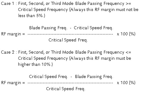
The resonant frequency margin with blade
passing frequency is obtained from below
formulas per the value in difference of
first, second, or mode blade passing frequency
and critical speed of drive shaft;
(6) Dynamic Balance: Dynamically balanced
spacers are necessary to keep the coupling
induced vibration to a minimum. Dynamic
balancing at operational speed is recommended
because long spacers can be considered as
flexible rotors. The dynamic balance classes
specified by AGMA Standard 515 are recommended.
|


