|
1) Torque Characteristic of NEMA Design B Motor
| All
AC induction motors will start by producing torque
in accordance with a specific speed versus torque
curve that is a function of the motor design and
applied voltage. The torque generated during starting
is divided among the fan load, the inertia loads
and friction losses. Fan loads are being changed
by the cube of the speed increase. The inertia
loads consist of the inertia of the motor, coupling
shaft, gear reducer and fan. The total inertia
is dominated by the fan inertia. As a result,
nearly all the torque generated during a start
is passed through the coupling shaft and gear
reducer.
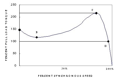 
The most common installation includes a single
speed, NEMA Design B motor with an across the
line starter. NEMA Design B specifies a minimum
locked rotor torque of 150% of rated full load
torque and a minimum breakdown torque of 200%
of rated full load torque. The motor produces
its breakdown torque shortly below full load speed.
At full speed, the torque transmitted is determined
by the fan load, which is normally less than rated
torque.
Flexible couplings for cooling tower applications
are commonly designed to accommodate 200% of full
load torque continuously and to withstand 300%
load for shorter periods. This additional capacity
allows for an over voltage to 110% of rated voltage.
Many gear reducers are designed in similar way.
Gear teeth damage begins to appear in the range
of 300% rated full load torque. At the breakdown
speed, the fan is just beginning to develop its
full load when the increased torque causes rapid
acceleration. This, in turn, leads to heavy loading
at the blade root, gear mesh and coupling.
|
2) Two Speed Motor
| The
torque characteristic of this type of two speed
motor for the application of the axial flow fan
is that the torque requirement increases as the
fan speed increases. This is a type of variable
torque load, which is proportional to motor speed.
Therefore, it is quite important to equip the
same type of torque load of motor.
If the constant torque motor was used for the
application of axial flow fan, the excessive torque
is unavoidable at the time of starting the motor
to the low speed by about 300% or more torque
to the full load torque.
Generally speaking, most of two speed variable
torque motors produce the breakdown torque in
the range of 280-300% of torque to the full load
torque when started in the high speed mode. These
motors will also generate this peak torque when
switched from low to high speed. Torque spikes
will result when switching from low to high speed
at the situation that there is no sufficient time
delay for the motor back EMF (Electrical Magnet
Field) to dissipate.

It is important to recognize the potential for
damage to both electric motors and the connected
equipment that will be caused by fast switching
or fast bus enclosure. The magnitude of torque
spikes generated during these occurrences can
be from 6 to 20 times the full load torque rating
of the motor. Changing speed or direction without
proper time delay presents the possibility of
generating damaging torque spikes. Due to the
large magnitudes involved, the damage caused can
be quite extensive. It is very evident that these
torque will bend or break drive shafts; mechanically
damage the motor winding; shear coupling keys;
break or damage gear teeth; fail fan blades at
the root.
When the power to the motor is interrupted, some
rotor current and flux becomes trapped in the
motor. This corresponds to a voltage characterized
as the back EMF of the motor and can be measured
at the motor terminals. This voltage decreases
with time at an exponential rate proportional
to the motor open circuit time constant. The phase
angle between this residual voltage and the power
system voltage also changes with time since the
induction motor speed is lower than the synchronous
speed of the power system. Thus, the magnitude
of the phase voltage difference between the motor
and the power system an be much greater just prior
to a reconnection than the magnitude of the power
system voltage when applied from a zero speed
start.
The transient electrical torque generated, when
an induction motor is connected onto a power system,
is dependent upon the speed at which the motor
shaft is rotating and by any electrical flux which
may have been trapped in the motor as a result
of a recent disconnection. If the load inertia
is large compared to that of the motor then the
transient part of the shaft torque can reach a
value equal to twice the magnitude of the change
in motor electrical torque.
The magnitude of the torque is so high they preclude
handling through mechanical safety factors. Instead,
circuitry should be used that allows time for
the back EMF of the motor to dissipate before
line voltage is reapplied. The use if power factor
correction capacitors lengthens the time to decay
the residual voltage in the motor. The time to
wait before a safe reconnection or restart is
lengthened when capacitors are used. Proper motor
control with sufficient time delays before making
any rotational or speed change is necessary to
prevent stress failure of mechanical components.
|
3) Shaft Failure
| The
following is a check list for determining the
probable cause of coupling failure with the two
speed motors:
- How many times are the motors switched
from stop to low speed, from low to high speed,
from high to low speed, or from low speed to stop
per hour?
(Generally the frequency
of changing the motor speed is limited to 6 in
order to prevent the excessive mechanical stress.
The electric motor will produce a breakdown torque
equal to approximately 250% of full load torque
each time the motor is started from the stop,
and also torque spikes equal to approximately
600 to 2000% of full load torque each time the
motor is switched from low to high unless the
proper time delay is used.
Excessive exposure to
the such high torque of the motor could fatigue
the coupling and cause the premature failure.)
- Motor Control Sequence
There are so many ways
to control the motor in accordance with the cold
water temp. It is quite essential to make a sequence
of motor control, which can limit the frequency
of motor speed change. The sequence chart attached
is typical for the cooling tower application and
the inspection of control panel is required if
the system is similar to the enclosed sequence
chart.
- Speed-Torque Curve of Motor
Most of NEMA design B
motors may be producing a much higher torque than
a standard rated motor. Potentially the motor
may have been derated and actually operates under
the conditions of a much larger motor. Check the
speed torque curve at both motor speed provided
by Motor manufacturer. It is our experience that
two speed motors develop a breakdown torque of
approximately 300% full load torque. The excessive
torque will make a coupling to break earlier.
- Type of Torque
Inspect the type of motor
torque. If the constant torque motor was applied
to the cooling tower, a greater motor torque than
the predicted torque of motor at the low speed
is produced and the shaft can be broken earlier
than the normal operation life time.
|
|


